TM 5-5420-234-14&P
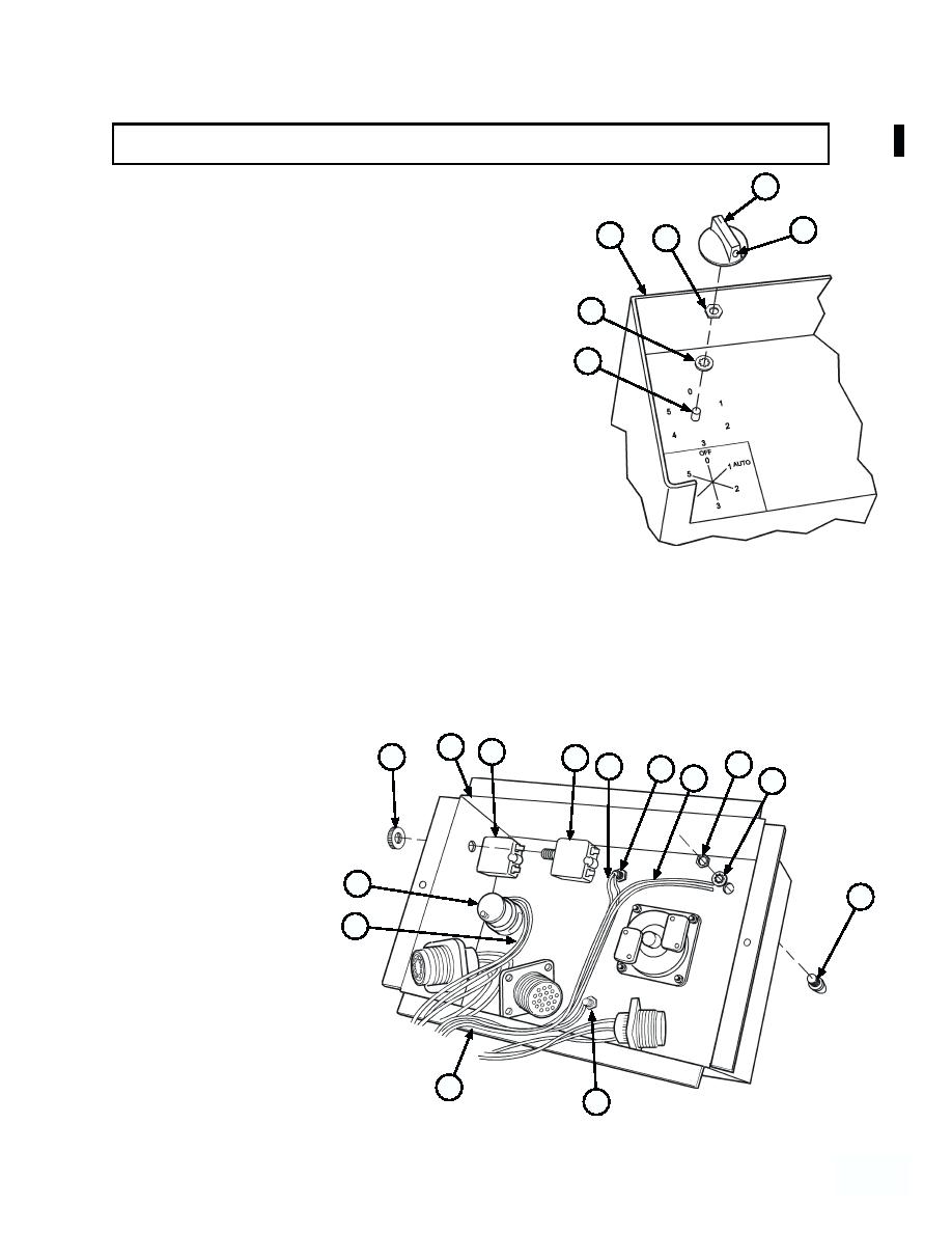
4-71. CAB CONTROL BOX ASSEMBLY REPAIR (MODEL A ONLY) (continued).
(4) Align matchmarks on rotary switch (38) and install
47
in cab control box (10) with lockwasher (49) and
nut (48).
46
10
48
(5) Install knob (47) on rotary switch (38) and tighten
screw (46).
49
38
(6) Install three indicator lights (36, 40, and 42) in cab
control box (10) with three lockwashers (45) and
nuts (44).
(7) Install two circuit breakers (30 and 31) in cab
control box (10) with three nuts (43).
(8) Solder wires (41) on indicator light (42).
(10) Solder wires (37) on rotary switch (38).
10
31
43
30
44
39
40
41
45
38
42
37
35
36
4--591
4 59 1
Change 1


