TM 5-5420-234-14&P
4-71. CAB CONTROL BOX ASSEMBLY REPAIR (MODEL A ONLY) (continued).
NOTE
Cut cable ties as required.
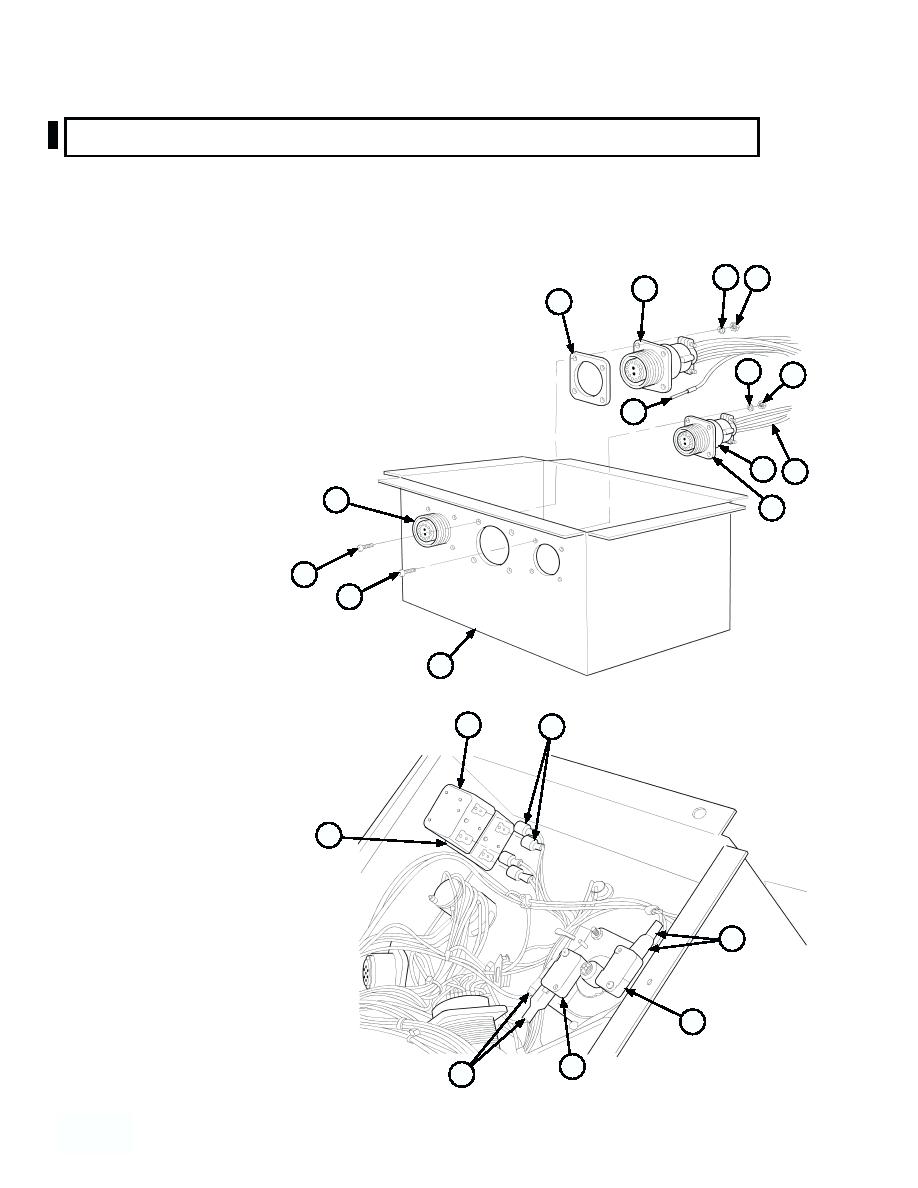
(5) Remove eight nuts (17), lockwashers (18), screws (19), two connectors (20 and 21) and gaskets (22) from
cab control box (10). Discard lockwashers and gaskets.
24 23
26
27
(6) Remove four nuts (23), lockwashers (24),
screws (25), connector (26) and gasket (27)
from cab control box (10). Discard
lockwashers and gasket.
18
17
(7) Remove terminals (28) from three
28
connectors (20, 21, and 26).
20 28
21
22
25
19
NOTE
Early production units have
three circuit breakers, one of
10
which is not connected.
(8) Disconnect four spade connectors (29)
30
29
from two circuit breakers (30 and 31).
(9) Disconnect four spade connectors (32)
from two switches (33 and 34).
31
32
34
33
32
4--588
4 58
Change 1


