TM 5-5420-234-14&P
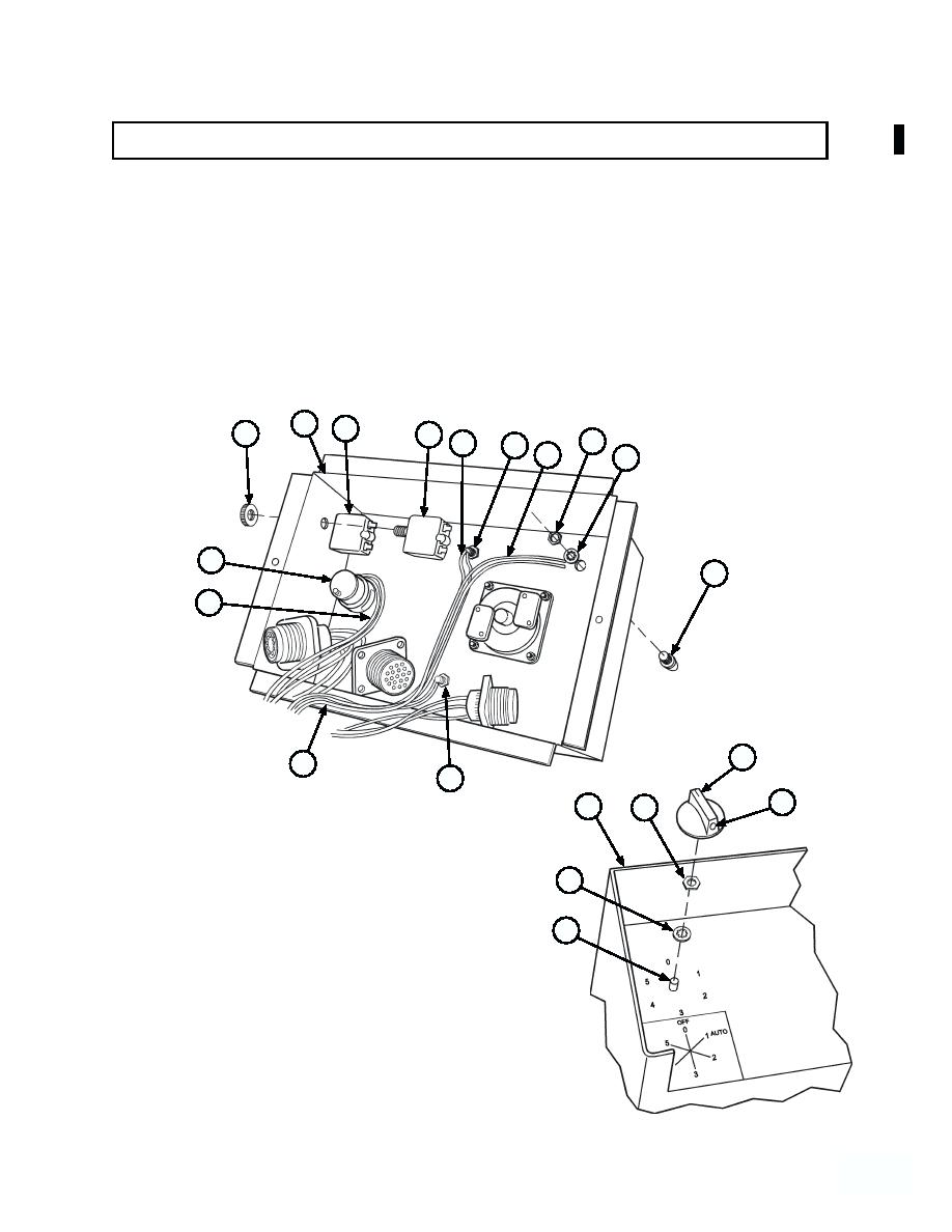
4-71. CAB CONTROL BOX ASSEMBLY REPAIR (MODEL A ONLY) (continued).
(11) Unsolder wires (37) from rotary switch (38).
(13) Unsolder wires (41) from indicator light (42).
(14) Remove two nuts (43) and circuit breakers (30 and 31) from cab control box (10).
(15) Remove three nuts (44), lockwashers (45) and indicator lights (36, 40, and 42) from cab control box (10).
10
31
43
30
44
39
40
41
45
38
42
37
47
35
36
46
10
48
NOTE
Rotary switch must be match
marked to ensure proper orientation
49
during assembly. Failure to comply
will result in incorrect LHS
functions for switch position.
38
(16) Matchmark rotary switch (38) to cab control
box (10).
(17) Loosen screw (46) and remove knob (47)
from rotary switch (38).
(18) Remove nut (48), lockwasher (49) and rotary
switch (38) from cab control box (10).
44589
--589
Change 1


