
TM 5-5420-234-14&P
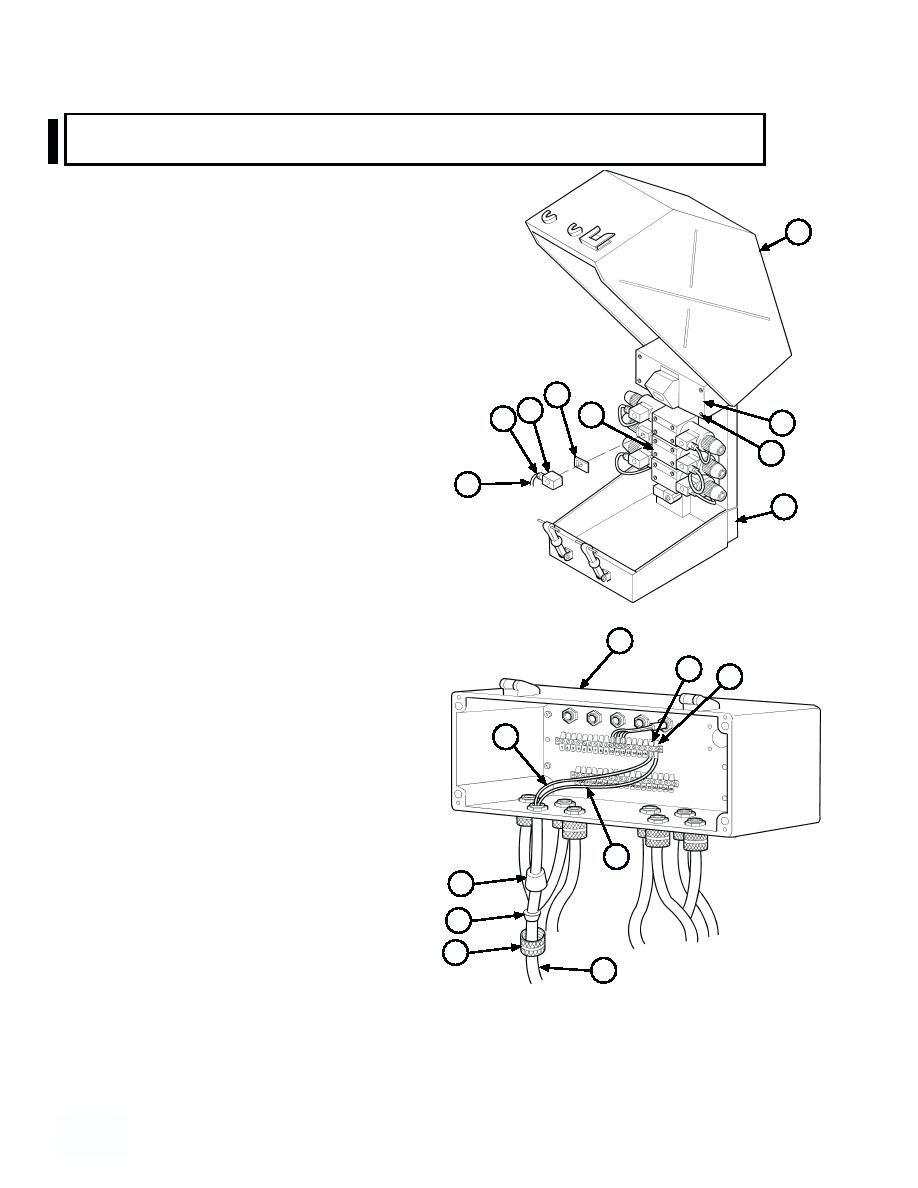
4-78. HOOK ARM VALVE (LOAD) HARNESS REPLACEMENT (MODEL A ONLY)
(continued).
NOTE
Tag and mark wires prior to removal.
1
Note position of rubber grommet prior to re-
moval.
(3) Remove white wire no. 17 (4) from terminal no. 17 (5)
and black wire no. 18 (6) from terminal no. 18 (7).
(4) Remove nut (8), plastic insert (9) and rubber grommet
(10) from junction box (11).
15
(5) Remove hook arm valve load harness (12) from
14
junction box (11).
16
13
3
(6) Loosen screw (13) and remove connector (14)
2
and gasket (15) from directional control valve
(16). Discard gasket.
12
17
(7) Remove nut (8), plastic insert (9), and rubber grommet
(10) from hook arm valve load harness (12).
b. Installation.
NOTE
Ensure rubber grommet is installed as noted
during removal.
11
5
Install cable ties as required.
7
(1) Install rubber grommet (10), plastic insert (9),
and nut (8) on hook arm valve load harness (12).
4
(2) Install new gasket (15) and connector (14) on
directional control valve (16).
(3) Position hook arm load harness (11) in junction
box (12).
(4) Install rubber grommet (10), plastic insert (9),
6
and nut (8) on junction box (11).
10
(5) Install black wire no. 18 (6) on terminal no. 18
(7) and white wire no. 17 (4) on terminal no. 17
(5).
9
(6) Close junction box cover (3) and tighten four
8
screws (2).
12
(7) Close hydraulic cabinet cover (1).
OTHER WIRE HARNESSES
REMOVED FOR CLARITY
c. Follow-on Maintenance:
Connect batteries (TM 9-2320-279-20).
END OF TASK
4-614
614
Change 1
