
TM 5-5420-234-14&P
2-16. HIGH-BANK BRIDGE BAY LAUNCH (continued).
24
NOTE
The slings and hardware required
for this operation are found in the
Bridge Supplementary Set, SC
5420-97-E51, NSN 5420-00-
071-5273.
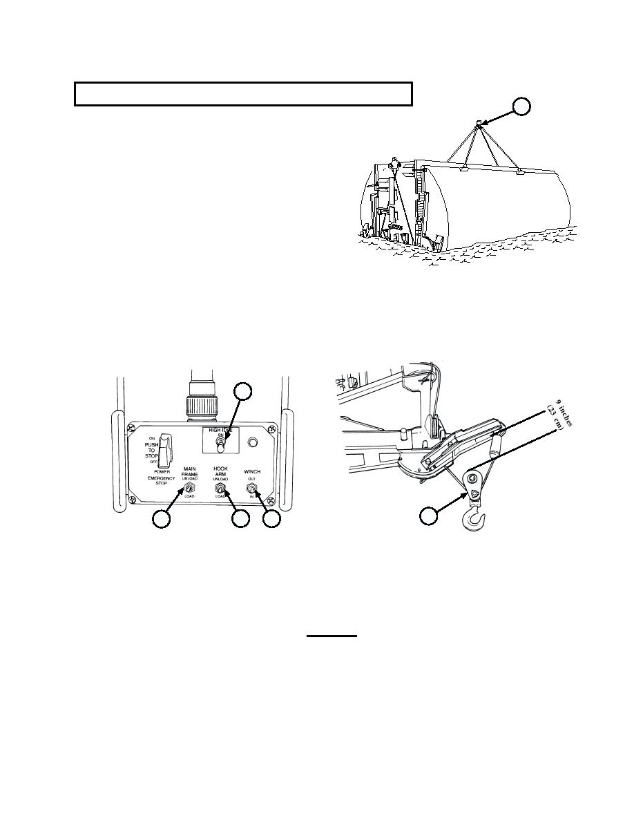
(16) Attach large ring of bridge bay sling (24)
to hook of snatch block (22).
(17) Turn HIGH IDLE switch (15) to ON.
(18) If this is an interior bay, attach intermediate cable hooks on two sling legs to large ring of sling.
(19) Position HOOK ARM switch (16) to LOAD and release when hook arm is fully retracted.
(20) Position remote WINCH switch (19) to IN and release when top of snatch block (22) is about 9 inches
(23 cm) from bottom of extension assembly (21).
15
22
16
19
18
(21) Position MAIN FRAME switch (18) to load and release when snatch block (22) is about 9 feet (2.8 m)
above ground.
(22) Turn remote HIGH IDLE switch (15) to OFF.
(23) Release parking brake.
CAUTION
Damage to equipment may occur if Transporter is backed up and the BAP
makes contact with bridge bay.
(24) Put transmission in reverse, back up Transporter, and stop when 6 to 8 inches (15.24 to 20.32 cm) of
clearance exist between bridge bay bow point and the closer part of BAP rear rollers (bumper or rear
rollers) or Transporter pintal hook assembly.
(25) Apply parking brake and place transmission in neutral.
2-89
