TM 9-2320-279-34-1
Axles No. 1 and No. 2 Maintenance Instructions (Cont)
9-13.
BALL SOCKET REMOVAL/INSTALLATION (CONT).
NOTE
Steps (7) through (13) are for both left and right sides.
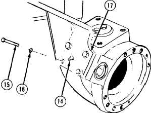
(7)
Remove grease fitting (14).
(8)
Remove four screws (15) and lockwashers (16).
(9)
Remove brake chamber mounting bracket (17).
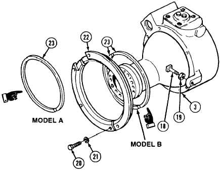
(10)
Measure and record length from top of stop bolt (18) to top of nut (19).
(11)
Remove nut (19) and stop bolt (18) from ball socket (3).
(12)
Remove six screws (20) and lockwashers (21).
NOTE
Seal halves are glued together and may be one piece on Model A or two pieces on
Model B.
(13)
Remove seal retainer (22) and seal (23).
9-84 Change 3