TM 5-5420-234-14&P
This task covers:
a.
Removal
b. Installation
c.
Follow-on Maintenance
INITIAL SETUP
Tools and Special Tools
Tag, Identification (as required) (Item 23, Appendix E)
Tool Kit, General Mechanic's: Automotive
Gasket (Item 109, Appendix K)
(SC 5180-90-N26)
Locknut (4) (Item 110, Appendix K)
Materials/Parts
Equipment Condition
Cable Ties (Item 8, Appendix E)
Batteries disconnected (TM 9-2320-279-20)
a. Removal.
1
NOTE
Cut cable ties as required.
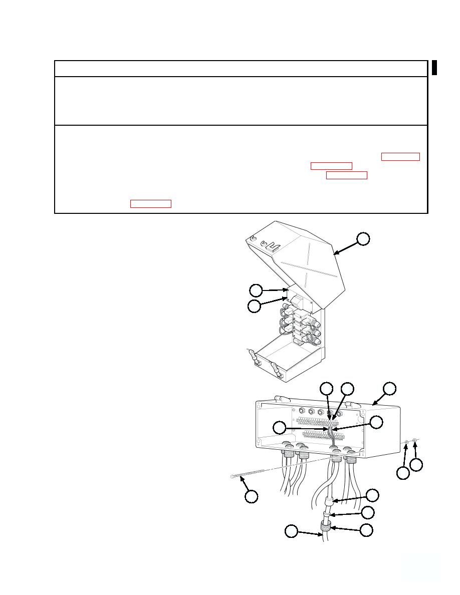
(1) Open hydraulic cabinet cover (1).
2
(2) Loosen four screws (2) and open junction box
3
cover (3).
NOTE
Tag and mark wires prior to removal.
(3) Remove white wire no. 15 (4) from terminal
no. 15 (5) and black wire no. 16 (6) from
5
11
7
terminal no. 16 (7).
(4) Remove four locknuts (8), washers (9) and
screws (10) from junction box (11) and gently
6
4
pull junction box forward to access nut (12).
Discard locknuts.
8
9
14
10
13
12
OTHER WIRE HARNESSES
15
REMOVED FOR CLARITY
Change 1
4 627


