TM 5-5420-234-14&P
4-64.1 DIGITAL CONTROL BOX AND RESISTOR ASSEMBLY REPLACEMENT
(MODEL B ONLY) (continued).
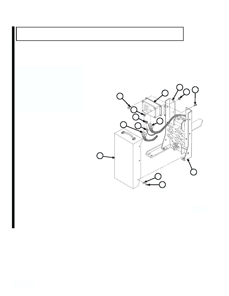
b. Installation.
NOTE
For resistor assembly replacement only, go
to step (1).
(1) Replace resistor (11) onto wiring harness (12).
(2) Position digital controller (8) on brackets (4)
and install three screws (5) from inside of
4
bracket (4) and one screw (6) from outside of
6
7
8
bracket (4). Secure with four self-locking nuts
5
(7).
(3) Position two wiring harness connectors (10) on
7
bottom of digital controller (8) and tighten two
allen screws (9).
11
10
(4) Position hydraulic cabinet cover (3) on main
9
12
junction box brackets (4) and secure with six
screws (1) and lockwashers (2).
3
4
2
1
c. Follow-on Maintenance:
Remove wheel chocks (TM 9-2320-279-10).
Connect batteries (TM 9-2320-279-20).
END OF TASK
4-572.2
4- 0
Change 1


