TM 9-2320-279-20-2
Brake and Air System Maintenance Instructions (Cont)
b. Adjustment.
(1)
(2)
(3)
(4)
(5)
(6)
Shut off engine (TM 9-2320-279-10).
WARNING
Muffler and connecting parts may be hot. Do not touch or lean against muffler. Serious
burns could result.
NOTE
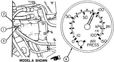
There are two kinds of air governors. Model A has the adjusting screw uncovered on the
bottom. Model B has a plastic cover threaded on the adjusting screw. Both are adjusted the
same way, however, the plastic cover on Model B must be removed before adjustment.
Loosen locknut (1) on bottom of governor (2). Turn adjusting screw (3) in to decrease cutout
pressure or out to increase cutout pressure.
Hold adjusting screw (3) and tighten locknut (1) to 80 to 120 lb-in (9.4 to 13.5 N°m).
Depress and release brake pedal enough times to reduce air pressure reading on gage to below
100 psi (690 kPa).
Start engine. Note pressure at which governor (2) cuts out. If further adjustment is needed, go
back to step (1).
NOTE
The plastic cover on Model B must be installed after adjustment is made,
Shut off engine (TM 9-2320-279-10).
C.
Follow-on Maintenance. None.
END OF TASK
Change 2
11-163


