
TM 5-5420-234-14&P
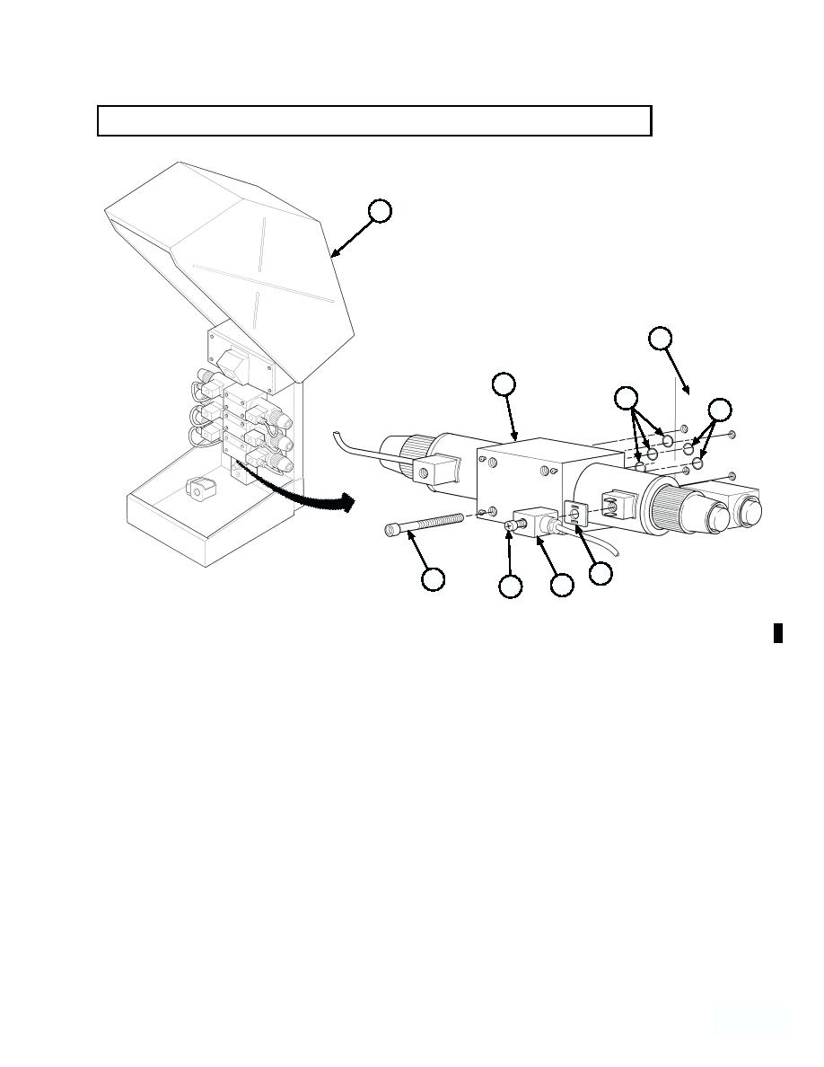
5-25. DIRECTIONAL CONTROL VALVE REPLACEMENT (continued).
1
8
5
~
7
7
4
6
3
2
MODEL A SHOWN
b. Installation.
NOTE
Coat O-rings with lubricating oil prior to installation.
(1) Install five new o-rings (7) and directional control valve (5) on main manifold block (8) with four screws
(6).
(2) Install two new gaskets (4) and connectors (3) on directional control valve (5) and tighten two screws (2).
(3) Close hydraulic cabinet cover (1).
c. Follow-on Maintenance:
Remove wheel chocks (TM 9-2320-279-10).
END OF TASK
Change 1
