TM 5-5420-234-14&P
4-12. UNIT TROUBLESHOOTING (continued).
13. MAIN FRAME DOES NOT LOAD IN MANUAL MODE (MODEL A ONLY)
(continued).
CONTINUITY TEST
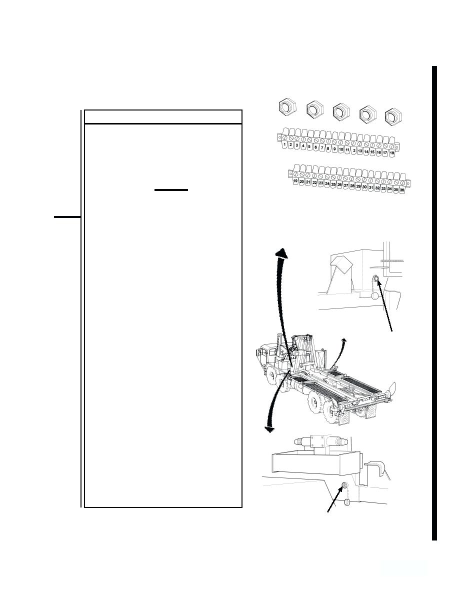
(1) Open hydraulic cabinet cover.
(2) Loosen four screws on main junction
box cover and open cover.
(3) If necessary, remove remote control
cable from linking harness connector.
CAUTION
Electrical power must be shut off
WIRING REMOVED
from circuit before continuity can
FORCLARITY
be checked. Failure to comply
with this caution may result in dam-
age to test equipment or electrical
system.
(4) Set multimeter to ohms position.
NOTE
A reading of infinity indicates an open
circuit.
(5) Connect multimeter to terminals at
RH LINKING
each end of wire, and check
HARNESS
multimeter for continuity. Check
CONNECTOR (J8B)
between terminal C on connector and
position 7 in junction box. Next,
check between terminal J on
connecter and position 23 in junction
box. Finally, check between terminal I
on connector and position 31 in
junction box.
NOTE
Any reading besides infinity indicates
a grounded wire.
(6) Check for grounded wiring by
connecting one multimeter lead to
each terminal and the other lead to
chassis ground.
LH LINKING
HARNESS
CONNECTOR (J8A)
4-247
Change 1


