TM 5-5420-234-14&P
4-12. UNIT TROUBLESHOOTING (continued).
13. MAIN FRAME DOES NOT LOAD IN MANUAL MODE (continued).
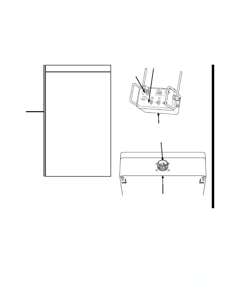
MAINFRAME
SWITCH
CONTINUITY TEST
EMERGENCYSTOP
(1) Disconnect remote control
SWITCH
cable from remote control unit.
(2) Set multimeter to ohms
position.
(3) Position EMERGENCY STOP
switch in the ON position.
(4) Have assistant hold the HOOK
ARM switch in the LOAD
position.
NOTE
REMOTE CONTROL
A reading of infinity indicates
an open circuit.
REMOTE CONTROL
CONNECTOR (J9)
(5) Connect multimeter leads to
remote control connector (J9),
positions "E" and "L" on remote
control unit, and check
multimeter for continuity.
(6) Repeat step 3, but this time
check for continuity between
positions "L" and "K".
REMOTE CONTROL
UNIT
Change 1
4-243


