TM 5-5420-234-14&P
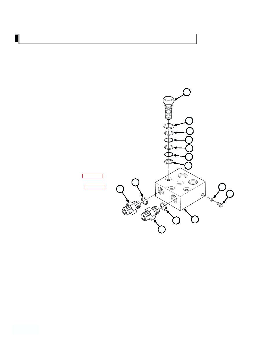
5-23. HOOK ARM MANIFOLD REPAIR (MODEL A ONLY) (continued).
b. Disassembly.
NOTE
Position manifold in soft-jawed vise to disassemble.
Note location of all components before removing.
11
(1) Remove two adapters (4) and o-rings (10) from hook
arm manifold (7). Discard o-rings.
(2) Remove two counterbalance valves (11) from hook
arm manifold (7).
16
(3) Remove and discard o-ring (12), backup ring (13),
13
two backup rings (14), o-ring (15) and o-ring (16)
from each counterbalance valve (11).
12
14
(4) Remove two plugs (17) and o-rings (18) from hook
arm manifold (7). Discard o-rings.
15
c. Cleaning/Inspection.
14
(1) Clean all parts. Refer to para 4-16.
10
18
(2) Inspect all parts. Refer to para 4-17.
4
17
(3) Replace all parts failing inspection.
7
10
d. Assembly.
4
NOTE
Lubricate O-rings and backup rings with clean lubricating oil prior to
installation.
Cup side of backup ring should face O-ring.
(1) Install two o-rings (18) on plugs (17) and install in hook arm manifold (7).
(2) Install new o-ring (16), o-ring (15), two backup rings (14), backup ring (13) and o-ring (12) on each
counterbalance valve (11).
(3) Install two counterbalance valves (11) in hook arm manifold (7).
(4) Install two new o-rings (10) on adapters (4) and install hook arm manifold (7).
5-140
5-
Change 1


