TM 5-5420-234-14&P
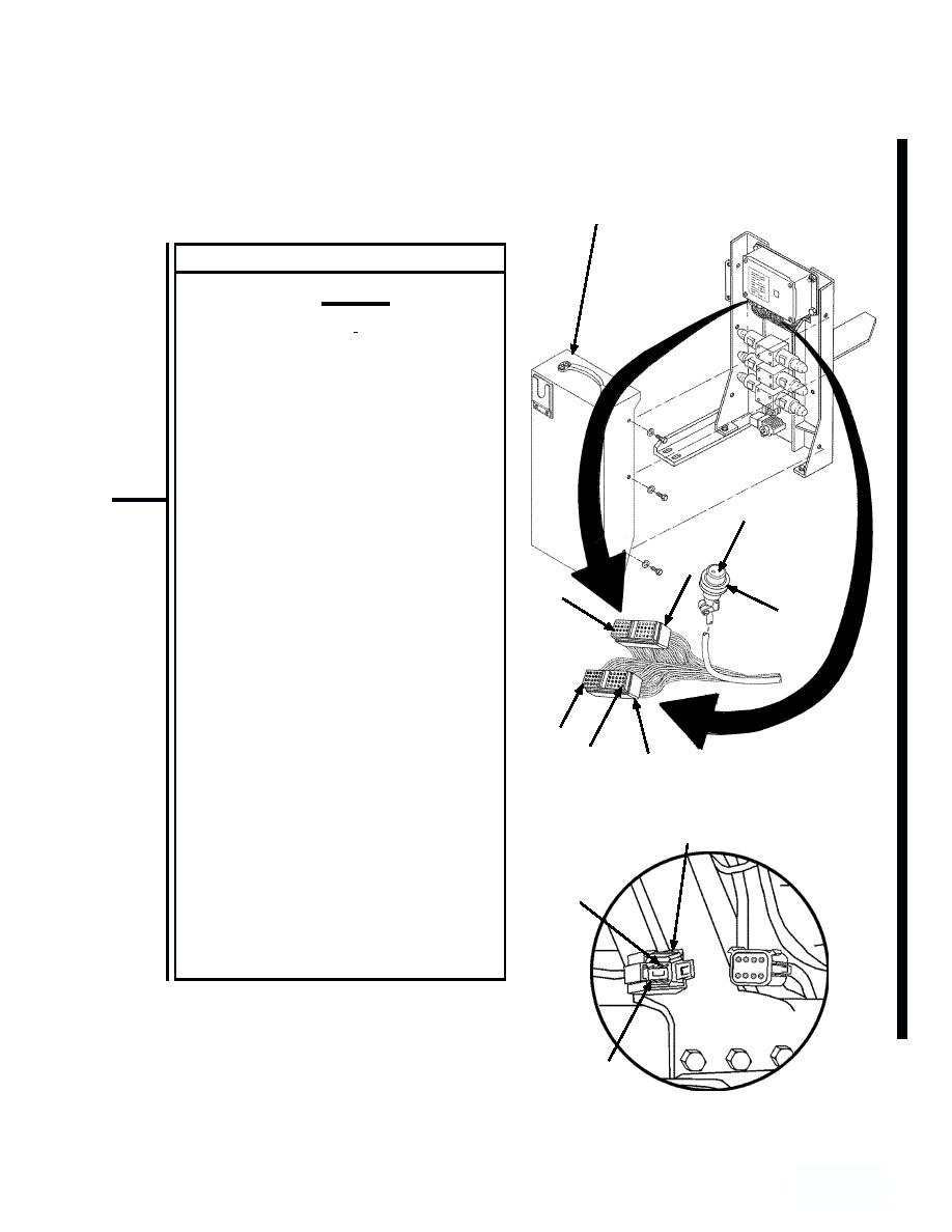
4-12. UNIT TROUBLESHOOTING (continued).
4.
MAIN FRAME WORKLIGHT DOES NOT OPERATE (MODEL B ONLY) (continued).
HYDRAULIC
CABINETCOVER
CONTINUITY TEST
CAUTION
Electrical power must be shut off
from circuit before continuity can
be checked. Failure to comply with
this caution may result in damage
to test equipment or electrical sys-
tem.
(1) Remove five screws and flatwashers
from hydraulic cabinet cover and
remove cover.
POSITION 1
(2) Remove right hand (J3) and left hand
(J4), 40-pin connectors from digital
contoller.
J3
(3) Disconnect main frame worklight
POSITION
wiring harness connector (J11) from
11
Digital controller wiring harness
P11
connector (P11), near bulkhead
connector.
(4) Set multimeter to ohms position.
NOTE
POSITION
A reading of infinity indicates an
1 POSITION
J4
open circuit.
10
(5) Connect multimeter between (P2),
position "2", and (J4), position "1".
P2
Check multimeter for continuity.
(6) Connect multimeter between (P2),
position "6", and (J4), position "10".
POSITION 6
Check multimeter for continuity.
(7) Connect
POSITION 2
Change 1
4-9494
45.5
- 9


