T M 9 - 2 3 2 0 - 2 7 9 - 3 4 - 1
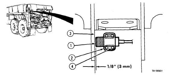
(4) Loosen four screws (4) and adjust mounting clamp (2) so mast overload switch (1) is 1/8 in.
(3 mm) from edge of mast (3). Tighten screws.
g . f o l l o w - o n M a i n t e n a n c e . Adjust overload sensor switches (para 17-33).
END OF TASK
Electrical System Maintenance Instructions (Cont)
f . M a s t O v e r l o a d S w i t c h I n s t a l l a t i o n ( M 9 77
o n l y ) .
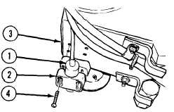
(1) Install mast overload switch (1) in mounting
clamp (2).
(2) Install mounting clamp (2) on mast (3) with four
screws (4).
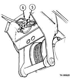
(3) Connect three wires (5) to connectors (6) (fig. 6-2).
6-69