TM 5-5420-234-14&P
4-12. UNIT TROUBLESHOOTING (continued).
14. MAIN FRAME DOES NOT UNLOAD IN MANUAL MODE (MODEL B ONLY)
(continued).
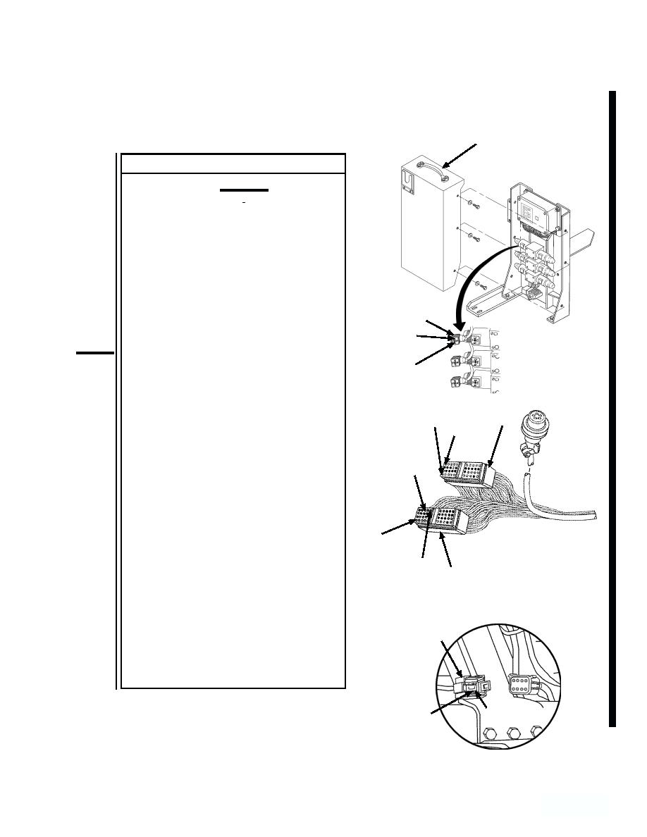
HYDRAULICCABINET
COVER
CONTINUITY TEST
CAUTION
Electrical power must be shut off
from circuit before continuity can
be checked. Failure to comply with
this caution may result in damage
to test equipment or electrical sys-
tem.
(1) Remove six screws and flatwashers
MAINFRAME
from hydraulic cabinet cover and
UNLOADSOLENOID
CONNECTOR
remove cover.
(2) Remove right hand (J3) and left hand
POSITION 1
(J4), 40-pin connectors from digital
contoller.
POSITION 2
(3) Set multimeter to ohms position.
NOTE
J3
POSITION 1
A reading of infinity indicates an
POSITION
open circuit.
31
(4) Connect multimeter between digital
POSITION
controller wiring harness connector,
33
(P2), position "2", and (J4), position
"1". Check multimeter for continuity.
(5) Connect multimeter between (P2),
position "3", and (J4), position "35".
POSITION
1
Check multimeter for continuity.
(6) Connect multimeter between (P2),
position "4", and (J4), position "33".
POSITION
J4
35
Check multimeter for continuity.
(7) Connect multimeter between (J3),
position "1", and main frame unload
solenoid connector, position "1".
Check multimeter for continuity.
P2
(8) Connect multimeter between (J3),
position "31", and main frame unload
solenoid connector, position "2".
Check multimeter for continuity.
POSITION 4
POSITION 3
Change 1
4-4-301
298.3


