
TM 5-5420-234-14&P
2-15. FREE BRIDGE BAY LAUNCH (continued).
16
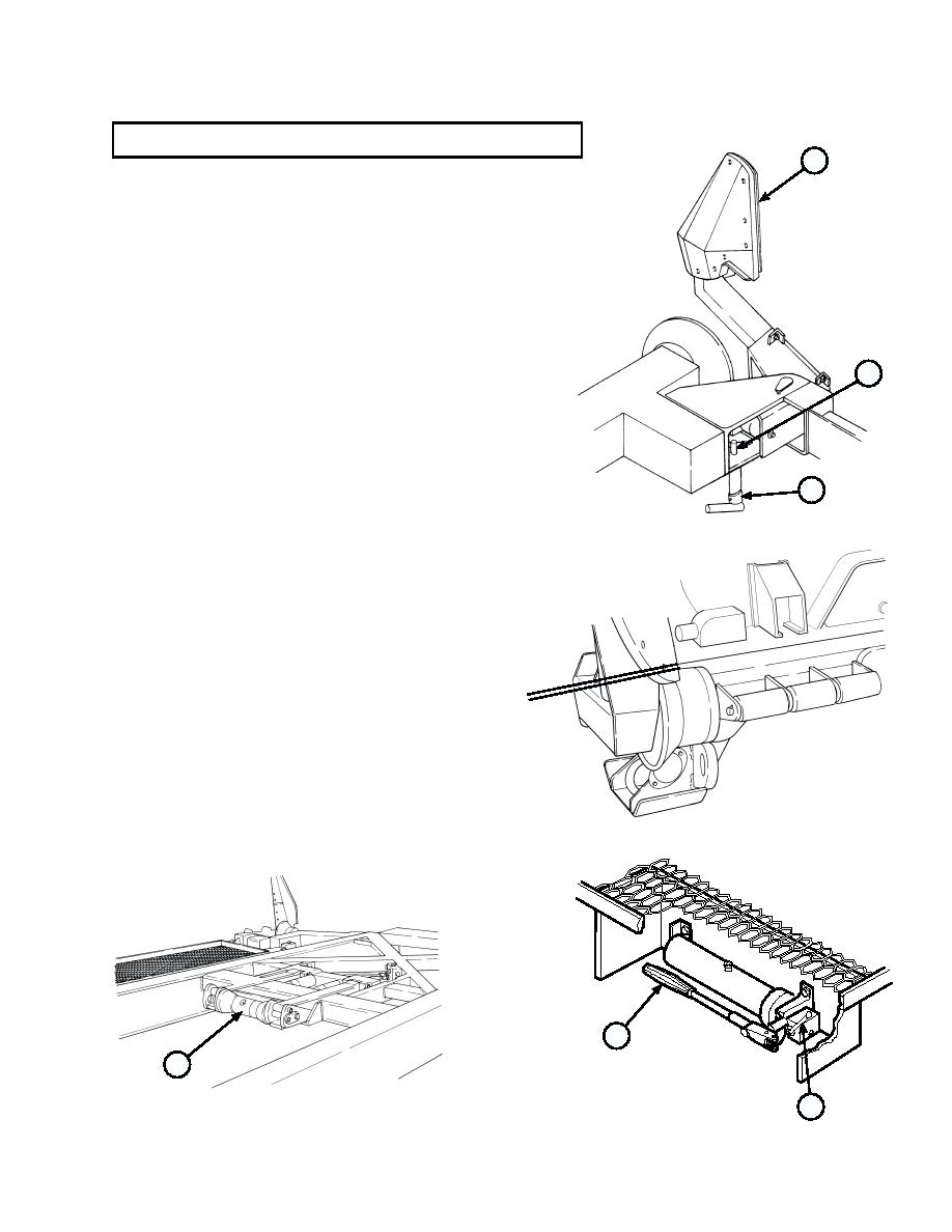
j.
Set curb-side and road-side rear guides (16) in the
disengage position:
(1)
Rotate latch pin (17) until rear guide (16)
disengages.
(2)
Swing rear guide (16) to fully open position, and
make sure pin (18) engages rear guide (16).
18
17
k. Raise center roller (19):
(1)
Place hand pump selector valve lever (20)
in center roller up position.
NOTE
There should be a 0.25-inch gap
(0.6 cm) between rear rollers
and ramp bay.
0.25 inch
(0.6 cm)
Interior bay does not require use
of hydraulic pump.
(2)
Pump hydraulic pump (21) until rear of
bridge bay lifts off rear rollers.
21
19
20
2-77

